|
|
|
|
Building Factory: Turbomeca (Francia)
|
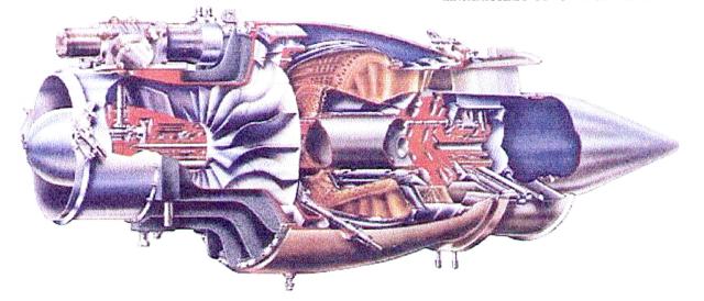
Type: pure turbojet with
single faced, single stage centrifugal compressor; annular combustion chamber and single
stage turbine.
|
Weight: 156 (+-3%) kgf.
|
Rotating sense: hourly, seen from the front.
|
Compressor: centrifugal single flow,
single stage done in aluminum alloy, with axial and radial diffusers.
Outer diameter: 382 mm. Theoretical compression ratio: 3.9:1 and air flow volume 8 kgf/seg @ 22 600 static RPMs. |
Combustion chamber: annular,
Nimonic 75 steel alloy made with centrifugal injection.
|
Turbine: axial single stage made of steel ATVS-7 alloy
with 37 milled blades and 25 hollow stators.
Inlet gas temperature: 780 °C. Outer diameter: 339 mm. Coefficient of total expansion in the turbine: 2,20 (What supposes a temperature fall of 150 °C). |
|
Exhaust nozzle: fixed without post-combustion, weight 6 kgf.
|
Main fuel system: it has a booster
pump, a main cut off valve, an up to 20 microns filter , a fuel control
unit equipped with a main pump with work pressure of 8 kgf/cm2 and
overspeed control, a pressure controller, an accelerator and an
altitude control. The fuel feeding system is from centrifugal injection type.
|
Fuel: aviation kerosene (JPl, JP4, Jet a/b or another one according
to norms).
|
Starting fuel system: it has a micropump with
a work pressure of 4 kgf/cm2 and two ignition torches.
|
Lubrication system:
10 liters oil reserve. It has a gears pump with a pressure of 4 kgf/cm2,
filter and recovery circuit.
|
|
Lubricant: mineral oil according to
norms.
|
Starting system: DC circuit of 27 Volts
(battery or auxiliary starting group). It has an electric starter with a resistance
system that allows two starting stages:
1st stage: 8 V, 250 amp. 2nd stage: 17V, 360 amp. |
Ignition system: DC circuit of 27 Volts.
It has two coils and two torches.
|
Air extraction system: it has an air
derivation from the combustion chamber for the fuel's entrance labyrinth pressurization
and two air extraction outlets at the compressor's carter upper side for the
airplane systems.
|
Back bearing refrigeration system: it has
a system of atmospheric cold air circulation.
|
| 1) |
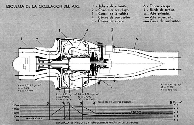
The first one, generally called primary flow, constitutes the combustion
air. It is divided in two currents:
- the first current passes between the cover of the diffusers and the front turbulence plate; the air penetrates in the combustion zone by three rows of radial grooves with tangential exit and inverse sense of exit from a groove to another one, to create a turbulence. - the second current circulates throughout the mixer of the outer part, penetrates in the hollow blades of the turbine stator and flows to the inner part of the combustion air chamber. This air that cools the turbine shaft when passing, arrives to the zone of combustion by hollowed orifices in the inner turbulence plate. |
| 2) |
The second, generally called secondary flow, constitutes the dilution air. It
penetrates in the interior of the mixer (flame tube), by oval tubes
and the four rows of holes perforated in the back part of the mixer.
It assures the dilution of combustion gases and cools them.
|
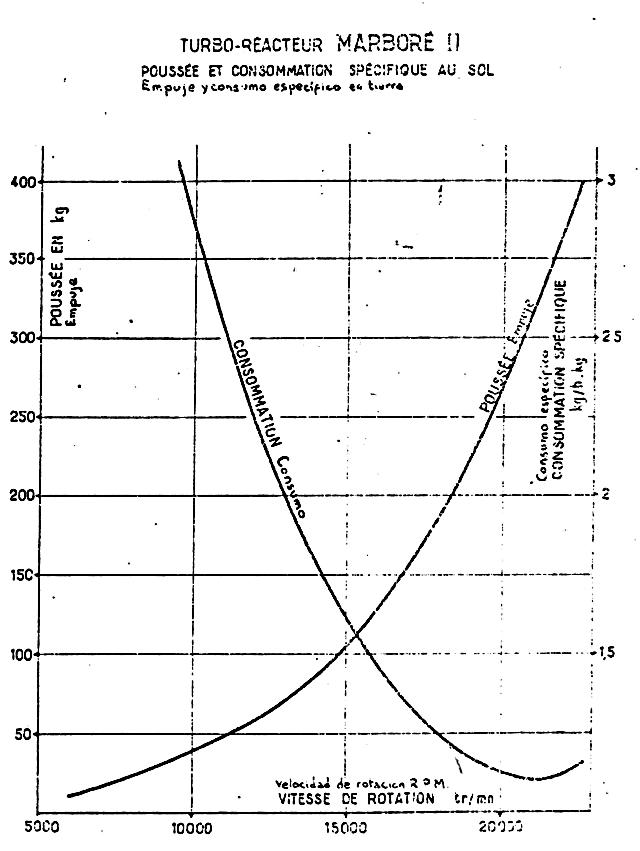
| Thrust: 400 (+-12) kgf. |
| Weight/thrust ratio: 0.402 kgf/kgfe. |
| Jet exhaust speed: 490 m/seg. |
| Jet exhaust temperature: 620°C. |
| Fuel consumption: 468 kgf/h (aprox. 585 lts/h). |
| Specific consumption: 1.090 kgf/kgfe/h. |
| Oil consuption: 0.2 kgf/h. |